Introduction
When we first began our studies at Haaga-Helia University of Applied Sciences, we were immediately intrigued by the world of IoT. Our journey started with the very first course, Internet of Things: A Business Perspective, where we explored different approaches to creating IoT solutions. From the beginning, our main goal was to develop a component of a weather station. From that point on, we were hooked.
We joined a course introduced by our teacher, Heikki Hietala, called the International IT Seminar for Students. In this class, we delved deeper into coding with Arduino and experimented with creating various devices, such as smartwatches and radio stations. One of the highlights was traveling to Spain with our classmates, where we connected with students from around the world and shared our knowledge of the IoT field.
In conclusion, while we had already gained some knowledge of IoT programming from previous classes, we remain eager to expand our skills and learn more each day.
Ideas
At the start of this project, we already had a pretty clear vision of what we wanted to create. Our goal was to build something fun and practical that could be used at student events, a playful gadget that works as a memorable party trick.
The first idea we had were:
- 1. IoT Truth or Dare Cube, A physical cube you shake, and the result is shown on a connected app with fun challenges.
- Elevator Prank box, A device you carry that automatically plays elevator music when you stop moving for more than 10 seconds.
- Plant Whisperer Mug, A mug that “talks” to your nearby plant via Bluetooth and shares fun plant updates when you drink near it (like “Your plant is jealous of your water”).
- Mood Doorbell, instead of a ding-dong, the doorbell plays random sound effects (lightsaber, goat scream, Mario coin) each time it’s pressed. You can update sounds via app.
- IoT Shoesoles, Measure how many steps you take in a day but instead of fitness stats, it gives random fun facts or jokes based on your steps.
But what we chose to continue this project with is a Sip ‘n’ Sense:
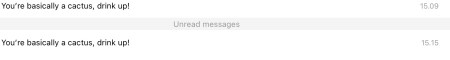
A cup that tracks how often you drink water and sends you random motivational or silly push notifications like “You’re basically a cactus, drink up!” What we’re going to do is add an alcohol content tracker that detects if there is alcohol in the mug. If the mug detects alcohol, it will send a message to your device with a hilarious message like “oh, it’s that kind of Monday huh?” etc.
What did we need to learn
At the beginning, we needed to learn how to use several new components and integrate them together: the ESP32 microcontroller, HC-SR04 ultrasonic sensor, MQ-3 alcohol sensor, GPS NEO-6M, infrared thermometer, push button, and WS2812B LED strip. We also had to learn how to program Telegram bots to send and receive notifications from our device.
The initial scope of the project was to create a playful IoT device called Sip ‘n’ Sense: a smart mug that could track how often you drink, detect alcohol content, measure temperature, and send witty push notifications to encourage hydration (or joke about drinking alcohol).
Our learning objectives included:
- Understanding and wiring different sensors (ultrasonic, alcohol, GPS, temperature).
- Programming ESP32 in the Arduino IDE and using libraries like TinyGPSPlus, UniversalTelegramBot, and Adafruit_NeoPixel.
- Designing and implementing a Telegram bot for user interaction.
- Calibrating sensors to produce meaningful readings.
- Measuring physical dimensions of the mug to calculate liquid levels accurately.
- Using 3D printing to create a lid that fits all components.
- Integrating LED lights to visualize the water level in a fun way.
The building phase
At the beginning of this class, our task was to build monitor lights and screens that could detect the distance between the monitor and an object. Here’s a short video collage showcasing the result. The components used in the project above included an I2C backpack for the LCD screen, Arduino, ultrasonic distance sensor, breadboard, cables, LEDs, jumpers, resistors, and push buttons. Enjoy.
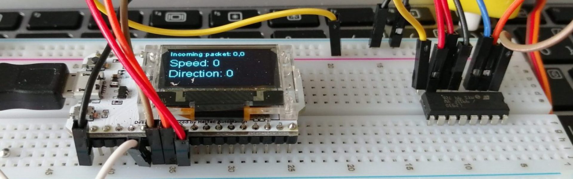
After completing that, we moved on to the next stage, the truly fun part of the class: building the device itself. The components used in this project included an MQ3 gas sensor, HC-SR04 ultrasonic sensor, NEO-6M GPS module, and an ESP32.
We started by naming the components on the breadboard: ESP, GPS, MQ3 ALKO and HC-UÄS and powering the board using the ESP32.
The HC –SR04 ultra sensor is connected as follows:
VCC – 5V
GND – GND
Trig – ESP32 (5)
Echo – ESP32 (18)
The alcohol sensor MQ-3 are connected as follows:
VCC – 5V
GND – GND
A0 – ESP32 (34)
The MQ-3 sensor requires a warm-up period, so it’s recommended to wait 20–60 seconds before taking measurements.

The next step was connecting the entire project to our computer and the Arduino IDE. We also installed the ESP32 library and Tiny-GPSPlus. We changed the Board to ESP32 Dev Module. To proceed, we needed to charge the battery of the MQ-3 alcohol sensor. We kept the device plugged in from Monday to Thursday. The HC-SR04 ultrasonic sensor and the MQ-3 alcohol sensor work seamlessly together within the same code. We still need to interpret the readings from the MQ-3 sensor. Next, we will focus on developing the Telegram bot.
Telegram bot:
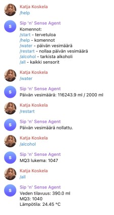
We decided that the device would send all notifications directly to the Telegram app on the user’s personal device. The name of our bot is Sip ‘n’ Sense Agent. For easier navigation and a shorter reference, we chose the username sipsense_bot. We used Telegram’s BotFather to create our own bot and generated an API token to access the HTTP API (8282242915:AAE5X0HZzxufftgeFMc_x0Xt9DlzCqjDFik). This token can be used by anyone to control our bot, so it must be kept secure. Here is the page: https://t.me/sipnsense_bot The chat ID is 6435133404. We included the library UniversalTelegramBot.
The code is working, and the Telegram bot is now functional. Currently, interacting with the bot requires entering a command such as /status to receive distance information. We are still testing to ensure everything works properly before integrating the device into the mug.
The cup we have has a capacity of 650 ml.

Next on creating a separate code to get the alcohol sensor functioning as well. The command to access it is /alcohol. The chatbot does answer the command, but we still need to figure out what the MQ-3 alcohol sensor value means. After a bit of research online, we found that if the value is below 3500, the drink contains alcohol. We merged the codes. The command for checking the amount of liquid is /water, and for alcohol, it is /alcohol.
The next step is to measure the cup. The following measurements are required:
- Height
Measure from the bottom of the cup to the lower edge of the lid (or the rim if there is no lid).
Use a ruler or measuring tape. - Diameter / Width
Top (opening): Measure across the widest part of the cup’s mouth.
Bottom: Measure the base diameter if it is smaller than the opening.
- Body Diameter at Different Points
If the cup narrows toward the bottom (conical shape), measure the diameters at a few points (e.g., at 1/3 and 2/3 of the height). - Lid Diameter and Height
If the cup has a lid, measure its width and height (if it extends above the cup). - Lid-to-Cup Connection
Measure how deep the lid fits into the mouth of the cup to ensure accurate volume calculation. - Curves / Textures
This is less often necessary for volume calculation, but for a more detailed model you can measure the height or depth of textured surfaces (this cup has an embossed pattern). - Cup Capacity
Confirm that the 650 ml capacity was measured at the correct level (full, without overflowing).
| Measurement | Value | Description |
| Height | 19.5 cm | Total height of the cup (without straw) |
| Lid | 8 cm × 1 cm | Lid diameter and lid height |
| Top diameter | 9.5 cm | Diameter across the top opening |
| Top width | 8 cm | Width of the cup at the top edge |
| Top circumference | 31.5 cm | Circumference of the cup at the top |
| Middle circumference | 28 cm | Circumference of the cup at the middle |
| Bottom diameter | 6.5 cm | Diameter across the bottom |
| Bottom width | 5 cm | Width of the cup at the bottom edge |
| Bottom circumference | 24 cm | Circumference of the cup at the bottom |
| Cup wall thickness | 1 cm | Thickness of the cup material |
| Bottom wall thickness | 2 cm | Thickness of the bottom cup material |
The first result showed that the mug’s capacity corresponds to 16.7 cm in height. We wanted to ensure that the cup accounts for its material, with a wall thickness of 1 cm on each side and 2 cm on the bottom. The liquid capacity measurement works. We poured some water into the cup and found that the capacity was 18.57 ml. Ultimately, the measurements we needed were the height of the cup, the height of the bottom wall, the volume in milliliters, the top diameter, and the bottom diameter.
We are still not entirely sure whether the alcohol sensor readings are as accurate as we would like. We decided that knowing the exact alcohol percentage is unnecessary; we only need to receive a notification when the cup detects alcohol.
Infrared thermometer
The next component we decided to add to our project was an infrared thermometer (model HW-691), which measures the temperature of the liquid inside the mug.
HW-691
VCC – 3.3V
GND-GND
SDA – GPIO21 (PC Data)
SCL – GPIO22 (PC Clock)
To enable the infrared thermometer, we included the Adafruit_MLX90614 library in our project. The thermometer functions correctly, as verified by comparing its readings with another thermostat and by measuring various objects, such as my hand. We added a single line of code to ensure the device sends all detected data to the bot. The message now includes all the data: water measurement, water temperature, and alcohol content.
Single press button
To ensure the bot provides the cup’s status, we added a single-press button to the device. When pressed, the sensor detects that the mug has been refilled. This was added because the sensor was previously picking up all liquid movements in the mug, sending us false information.
Single press button – GPIO23
GND – GND
3D printing
We wanted to assemble the entire mug so that all the parts fit securely together. To achieve this, our teacher 3D-printed a new lid for the mug, which already had holes for the HC-SR04 ultrasonic sensor.

LED-strip
As we progressed, we chose to integrate LED strip lights (WS2812B-LED) to visually indicate the mug’s fill level. We added the Adafruit_NeoPixel library to make the LED strip work. The LED strip receives data from the HC-SR04 ultrasonic sensor and illuminates the LEDs up to the corresponding level. We assigned color indicators to the levels: blue for full, green for half, and red for almost empty or empty. The slot on ESP32 is GPIO 27
We know the measurements of the mug: 19.5 cm tall, with a top circumference of 31.5 cm and a bottom circumference of 24 cm. Its total capacity is 650 ml. The mug is wrapped with a WS2812B LED strip containing 38 LEDs, placed approximately evenly around its surface. Our goal is to have the LEDs visually indicate the waterline, showing how full the mug is at any given time. The next step is to determine the best way to structure and configure the device so the LED display accurately represents the water level.
The LED strip now displays the water level inside the mug: green LEDs represent the filled portion, while pink LEDs indicate the empty space above the water.

We integrated a light function for the alcohol sensor. Whenever the device detects alcohol, the LEDs flash red for 10 seconds every minute, continuing as long as alcohol is present in the mug. For practical use, we modified the code so that all functions remain active for a duration of 5 minutes.
The outcome
The outcome of the project was a working prototype that we are proud of. The mug can successfully detect its water level using the ultrasonic sensor, measure whether there is alcohol in the drink, read the temperature of the liquid with the infrared thermometer, and display the water level visually using LED lights. It sends information directly to our Telegram bot, where we can use simple commands such as /water, /alcohol, and /status to get live updates. While we initially planned to include GPS tracking, we decided to leave it out in the final version to keep the project simpler and more practical.

Through this project, we learned a great deal about IoT development. We gained hands-on experience in wiring, troubleshooting, and calibrating sensors, and we learned how to work with the ESP32 microcontroller to combine data from multiple inputs. We also learned about integrating software and hardware by building a Telegram bot and connecting it to our mug, and about how 3D-printed components can be used to make custom enclosures for electronics. Most importantly, we learned how to keep a project moving forward by solving problems as they came up, such as when our sensors weren’t working due to cable issues or when we needed to simplify our design to make it practical.
This course definitely made us more interested in tinkering. The process of experimenting with code, wiring up sensors, and seeing the mug slowly come to life was very satisfying and has inspired us to keep building new things. It didn’t feel like a one-off project but rather a starting point for exploring IoT further.
In the future, we have many ideas for continuing this work. We would like to create a fully wireless and rechargeable version of the mug, add Bluetooth connectivity to make it easier to pair with smartphones, and perhaps even connect it to a health tracking app so it can automatically log daily water intake. Additionally, the project could include programmable LED light patterns, GPS functionality, and sound features to enhance interactivity and user experience. We are also interested in building some of the other devices we brainstormed at the start of the course, such as the IoT Truth-or-Dare Cube or the Mood Doorbell, and exploring how the same concept could be applied to other fun gadgets, like plant pots that light up to show soil moisture levels.
✨ Brought to life by the unstoppables: Katja Koskela and Inka Lindström
Finished on 9.10.2025 after way too many energy drinks 🧃
🚀 We hope you love it as much as we loved building it!